Figure 1: 2-D unwrapped hydrogen/air RDE simulations
The highly efficient rotating detonation engine (RDE) has been considered as one of the viable replacements for current propulsion and power generation systems that employ constant pressure combustion. In this project, simulations based on the generic framework for blockstructured Adaptive Mesh Refinement in Object-oriented C++ (AMROC) are conducted to study the problems in RDE, i.e., premixed and non-premixed injection, multi-waves mode and wavelet features, etc.
The RDE, which employs pressure-gain combustion, is able to operate with limited
or no mechanical compression. The detonation wave rapidly propagates in the
combustor resulting in a nearly constant-volume combustion process that produces
high-pressure burnt products and provides the thrust.
In order to reduce the computational cost, a 3-D annulus RDE can be unwrapped
into a 2-D plane. The 2-D Navier-Stokes equations with detailed chemical kinetics
are solved based on a Cartesian mesh in AMROC -Clawpack. A second-order accurate
MUSCL-Hancock scheme with Minmod limiter is used for the reconstruction. A hybrid
Roe-HLL Riemann solver is utilized to evaluate the inviscid fluxes. For multi-dimensional
problems, the hybrid Roe-HLL solver is combined with the wave propagation method.
|
|
Figure 1: 2-D unwrapped hydrogen/air RDE simulations |
The premixed hydrogen/air RDE and ethylene/oxygen RDE are tested with continuous and discrete injection, respectively.
 |
|
Figure 2: 2-D unwrapped ethylene/oxygen RDE simulations |
https://eprints.soton.ac.uk/424507/
https://eprints.soton.ac.uk/436419/
![]()
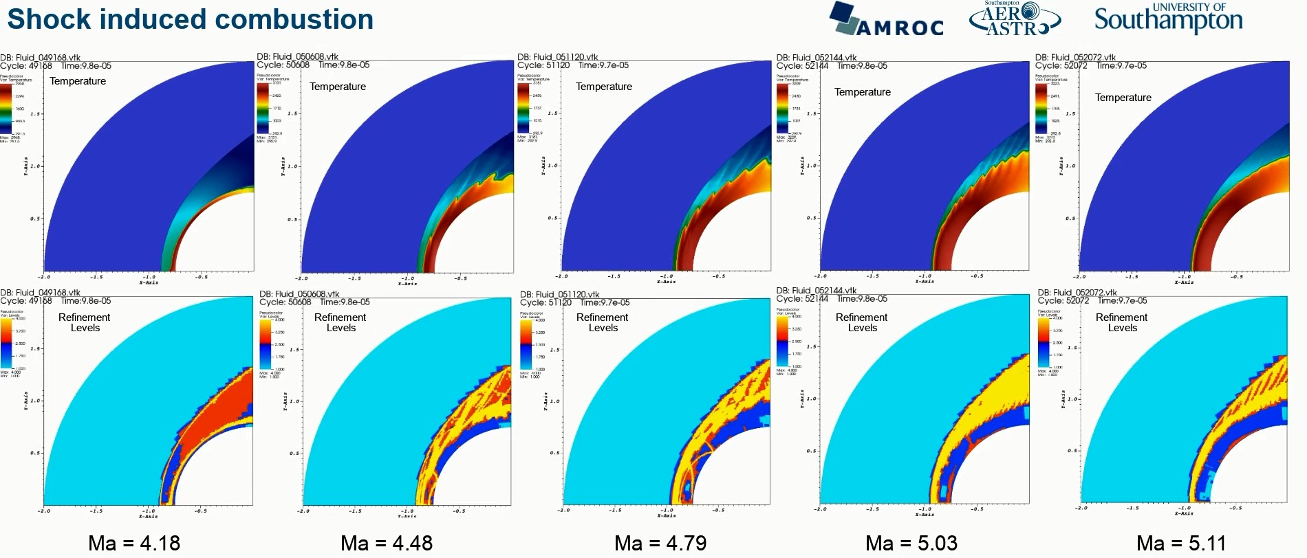
Shock-induced combustion (SIC) is a phenomenon that the combustion is self-ignited by a shock wave in a reactive mixture. In this project, simulations based on the generic framework for blockstructured Adaptive Mesh Refinement in Object-oriented C++ (AMROC), are extended for the mapped meshes. The unsteady SIC problems at varying Mach number are simulated with detailed chemical-kinetic mechanisms.
In the unsteady SIC problem, the shock is generally driven by a wedge or spherical
projectile travelling at a high velocity. The unburned mixture behind the shock
is compressed, as a result, chemical reactions are triggered.
A generic solver in our structured adaptive mesh refinement framework AMROC-Clawpack
is extended to simulate this problem on a non-Cartesian mapped mesh. A second-order
finite volume method is used with a grid-aligned Riemann solver for inviscid
thermally perfect gas mixtures. To solve this reactive problem, detailed chemical
kinetics are employed with a splitting approach. The prolongation and restriction
operators are modified to implement the adaption algorithm on a mapped mesh.
 |
|
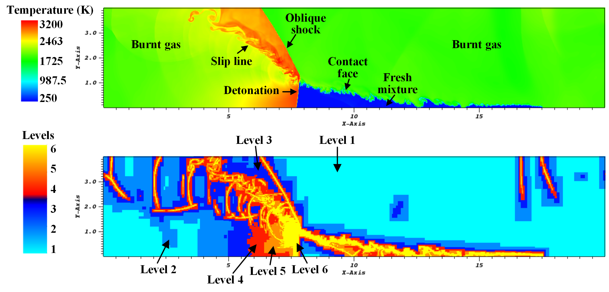
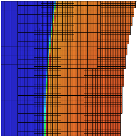
Figure 1: Temperature and refinement levels distribution
|
The mesh is refined at the places where there is a large gradient of physical variables. All the waves and the reaction front are captured by the finest mesh.
 |
|
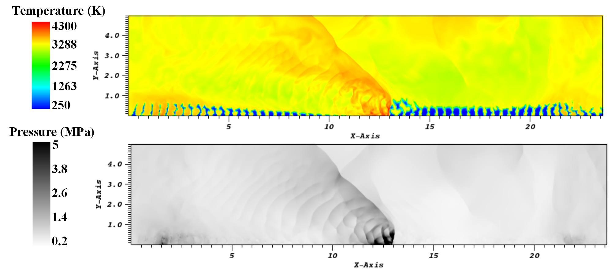
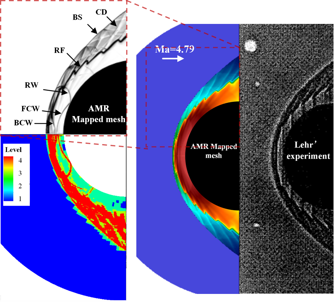
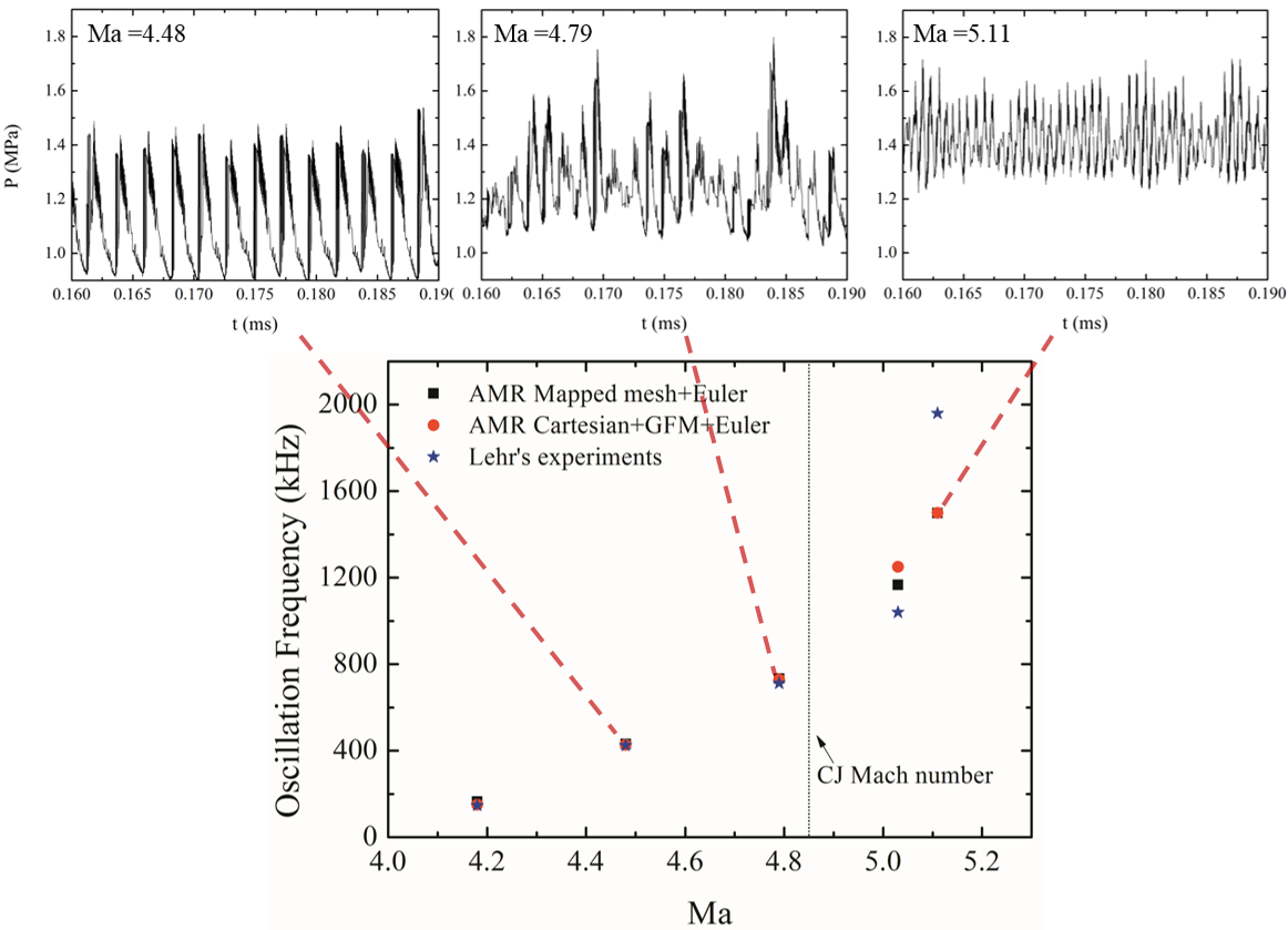
Figure 2: Comparison between simulation and experiment
|
|
In the simulations, the shock wave and reaction front stand-off distance is similar with that in a previous experiment. The computed oscillation frequencies, observed in the stagnation point pressure, are in good agreement with the frequencies from experiments when the inflow is subdetonative.
|
 |
|
|
![]()
Strand/Cartesian AMR meshes applied to surface motion problems
Vehicles travelling at hypersonic speeds experience significant heat transfer from the surrounding flow. This can require the use of thermal protection systems that ablate at high temperatures to reduce the heating experienced by the vehicle. Ablation leads to shape change, which can cause bottlenecks in computational simulations as a new computational mesh is required. This project is investigating the use of strand/Cartesian AMR meshing procedures to automatically create high-quality grids around ablating bodies.
Cartesian Adaptive Mesh Refinement (AMR) and strand mesh algorithms are two largely automated procedures that can be used to discretise the computational domain in fluid simulations.
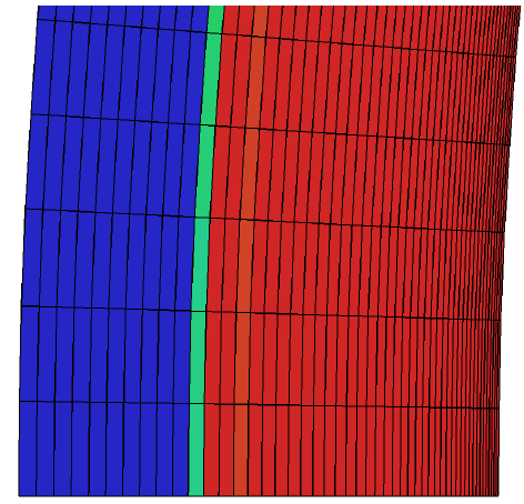
Cartesian AMR algorithms are able to resolve important flow features in an
automated and efficient manner. This is achieved through mesh refinement in
areas of interest, such as where there are high gradients or large discretisation
errors. However, the Cartesian structure often leads to approximations in the
surface geometry, which can distort the boundary layer and lead to inaccuracies
in surface results (heat flux, shear stress).
 |
|
Figure 1: Shock resolution and surface representation
with an AMR mesh.
|
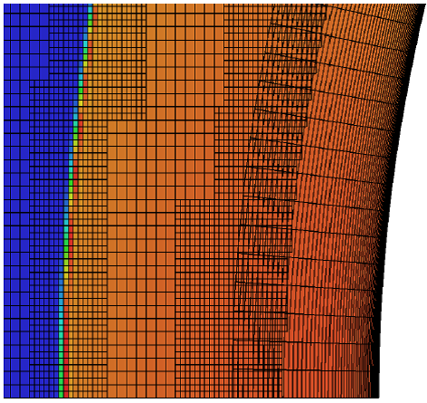
Strand mesh algorithms create a mesh by growing strands from an arbitrary surface and then joining nodes on the strands to make computational cells. Strand meshes can accurately represent a surface geometry and can incorporate stretching in the wall normal direction to improve the accuracy of surface results for a set number of cells. However, the strand mesh cannot resolve flow features automatically and there are limitations to how far from the surface the strands can grow, for example when strands cross.
 |
|
Figure 2: Shock resolution and surface representation
with a strand mesh.
|
The advantages of the two meshing paradigms can be combined using overset (a.k.a. Chimera) meshing techniques to join a near-body strand mesh with an off-body Cartesian AMR mesh. Overset algorithms enable separate computational domains to be joined together using boundary conditions. The boundary conditions from one domain are set using interpolated data from another domain. The combination of the two meshes enables meshes to be automatically created that highly resolve off-body flow features and boundary layer flows.
 |
|
Figure 3: Shock resolution and surface representation
with an overset strand/Cartesian AMR mesh.
|
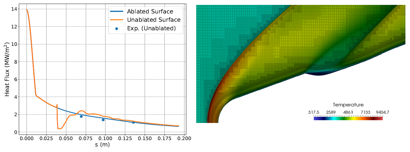
In this research, the AMROC Cartesian AMR framework has been extended to include a hypersonic fluid model (two-temperature model). The Cartesian solver has been adapted to enable the use of body-fitted meshes that can be created using strand generation algorithms. Overset methods have been implemented to enable efficient, parallel point-to-point communication between overset meshes, utilising existing features of the AMROC framework where possible. The overset strand/Cartesian AMR solver has been validated using experimental heat flux results and the automated meshing procedure has been demonstrated using a range of geometries.
 |
|
Figure 4: Demonstration of heat flux results when
using a strand/Cartesian AMR mesh around an ablated body.
|
https://eprints.soton.ac.uk/439165/
https://eprints.soton.ac.uk/420989/
![]()
The lattice Boltzmann method is known for its computational efficiency and low numerical dissipation properties. Nonetheless, it is restricted to Cartesian grids, making this approach remarkably expensive for capturing boundary layers, and thereby impractical for external flow problems. This PhD project has been funded by CONACYT.
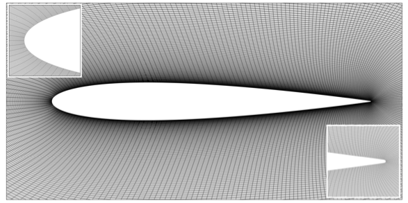
In this work, a second-order numerical scheme is implemented to solve the discrete-velocity Boltzmann equation in generalised curvilinear coordinates to perform fluid flow simulations with non-uniform grids.
 |
 |
|
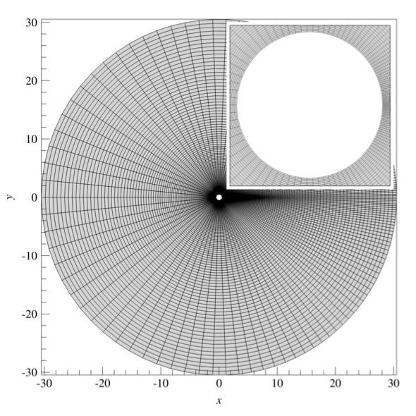
Two-dimensional flows over a circular cylinder and NACA0012 aerofoil are specifically investigated to assess the accuracy and performance of the proposed approach. Additionally, the present method has been compared to our own standard Cartesian lattice Boltzmann solver with adaptive mesh refinement (AMROC-LBM) to demonstrate its advantages over the latter. |
 |
|
The present approach can resolve accurately large gradients
in the wall vicinity with fewer mesh elements, which may lead to a dramatic
reduction in computational effort over Cartesian lattice Boltzmann solvers.
|
https://eprints.soton.ac.uk/435492/
https://eprints.soton.ac.uk/442223/
Juan Antonio Reyes Barraza
![]()
The research focuses on high-fidelity dispersion modelling within atmospheric flows in cases such as urban environments. The project is in partnership with Dstl.
Prediction of chemical and biological hazards have a substantial benefit to public safety. These hazards can come from many sources. Examples could be a chemical or biological agent released into crowded public spaces. In scenarios such as these hazard prediction within minutes or hours can become very useful. The current simple methods used by the industry have their weaknesses when trying to produce realistic dispersion cases.
To get around this, more robust methods such as CFD with RANS and LES to capture the full dynamics of problem are nowadays employed. An alternative to using traditional large run-time CFD schemes is the lattice Boltzmann method (LBM). LBMs have many advantages to traditional CFD. One of which is that it is readily suited for parallel processing, thus, allowing for quick results. These parallel processing can be done on graphic processing units (GPUs).
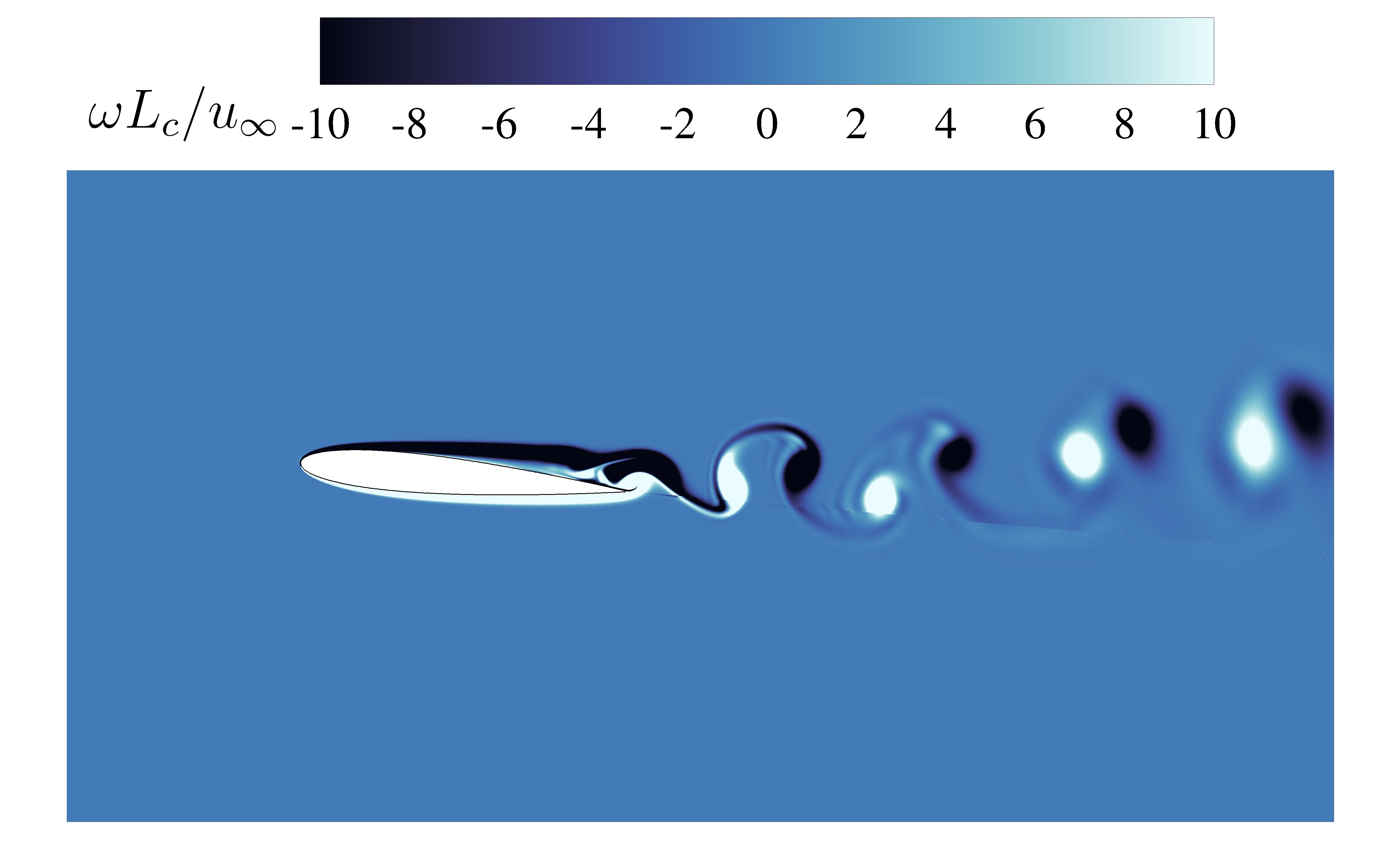
The focus of this research is to implement an LBM code on GPUs for dispersion
prediction which fully incorporates atmospheric and turbulent behaviour in complex
environments. The dispersion modelling is done with passive scalar assumptions.
 |
|
3d Cylinder Dispersion Case, Velocity (Top), Dispersion
(Bottom)
|
![]()
This work has been funded by the Southampton-FAPESP SPRINT - Sao Paulo Researchers in International Collaboration and University of Southampton (FAPESP grant 2016/50016-9).
The overarching objective of this multidisciplinary project was the development of a three-dimensional parallel dynamically adaptive numerical method that permits fast and reliable space weather magneto-hydrodynamic simulations.
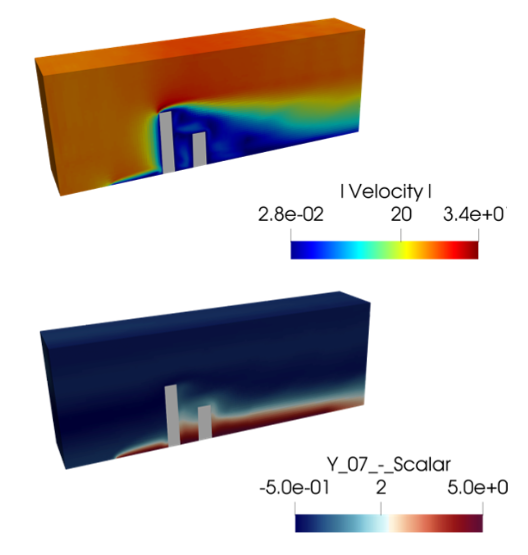
Plasma disturbances affect satellites and spacecraft and can cause serious problems to telecommunications and sensitive sensor systems on Earth. In order to predict such perturbances, a novel wavelet-based multi-resolution simulation solver for magneto-hydrodynamics has been developed in the parallel blockstructured adaptive mesh refinement framework AMROC, cf. Fig. 1. Such simulations are vital for predicting the interaction of solar wind activity with the Earth magnetic field and thereby the interference of ionized plasmas from the sun with modern communication satellite technology.
 |
|
Fig 1: Steady-state magnetosphere predictions obtained, respectively, from northward- (top) and southward-oriented (bottom) interplanetary magnetic field using an adaptive mesh. Left: density solution (in n/cc) with magnetic field lines. Right: regions of adaptation levels. |
https://eprints.soton.ac.uk/431950/1/amr_mhd_0519.pdf
Pure project ID: 516132101
Müller Moreira Lopes (National Institute for Space Research (INPE), São José dos Campos, São Paulo, Brazil)
Margarete Oliveira Domingues (INPE, São José dos Campos, São Paulo, Brazil)
Odim Mendes (INPE, São José dos Campos, São Paulo, Brazil)
![]()
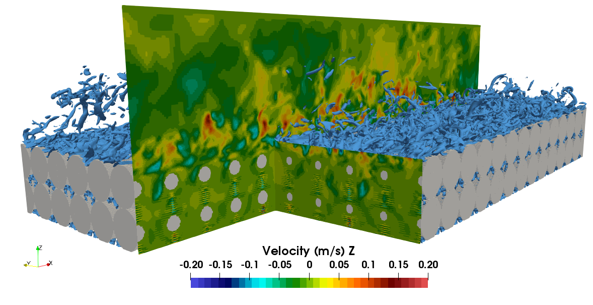
Flows over porous and rough media can be found in nature and in industrial devices and are attracting growing interest. The combination of permeability and roughness effects can be beneficial or detrimental to the aerodynamics or aeroacoustics properties of a permeable and rough system. In this project, we employ the lattice Boltzmann method (LBM) and adaptive mesh refinement (AMR) to enable accurate aerodynamics and aeroacoustics simulations of such flows. This project is part of EPSRC grant Aerodynamics and Aeroacoustics of turbulent flows over and past permeable rough surfaces (EP/S013296/1).
This project has several objectives. In cooperation with our project partners,
we investigate various permeable and rough scenarios. By combining our LBM-LES
approach with the experimental and DNS approaches of our colleagues, we aim
at providing a better understanding of the physics of turbulent flows over and
past rough and porous media. The ultimate goal is to exploit aerodynamics and/or
aeroacoustically beneficial effects of these flows for industrial applications.
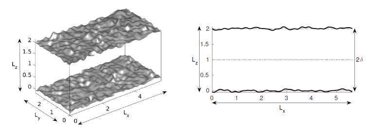
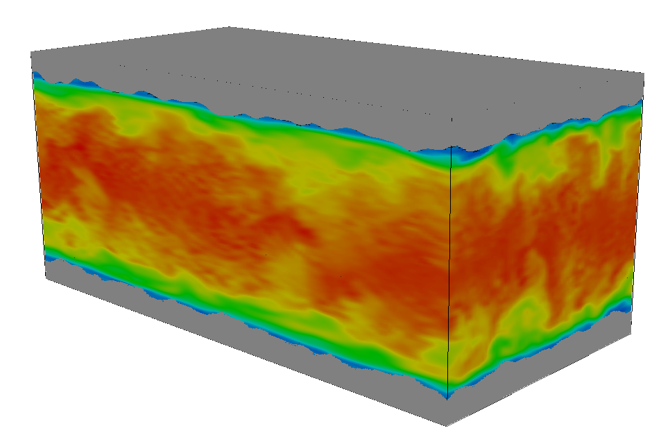
Using our in-house code AMROC-LBM, we have already been able to validate our
approach for modelling turbulent flow over a rough and porous medium made of
several spheres layers at Reynolds number 17,630, Fig. 1 and 2. A first aeroacoustics
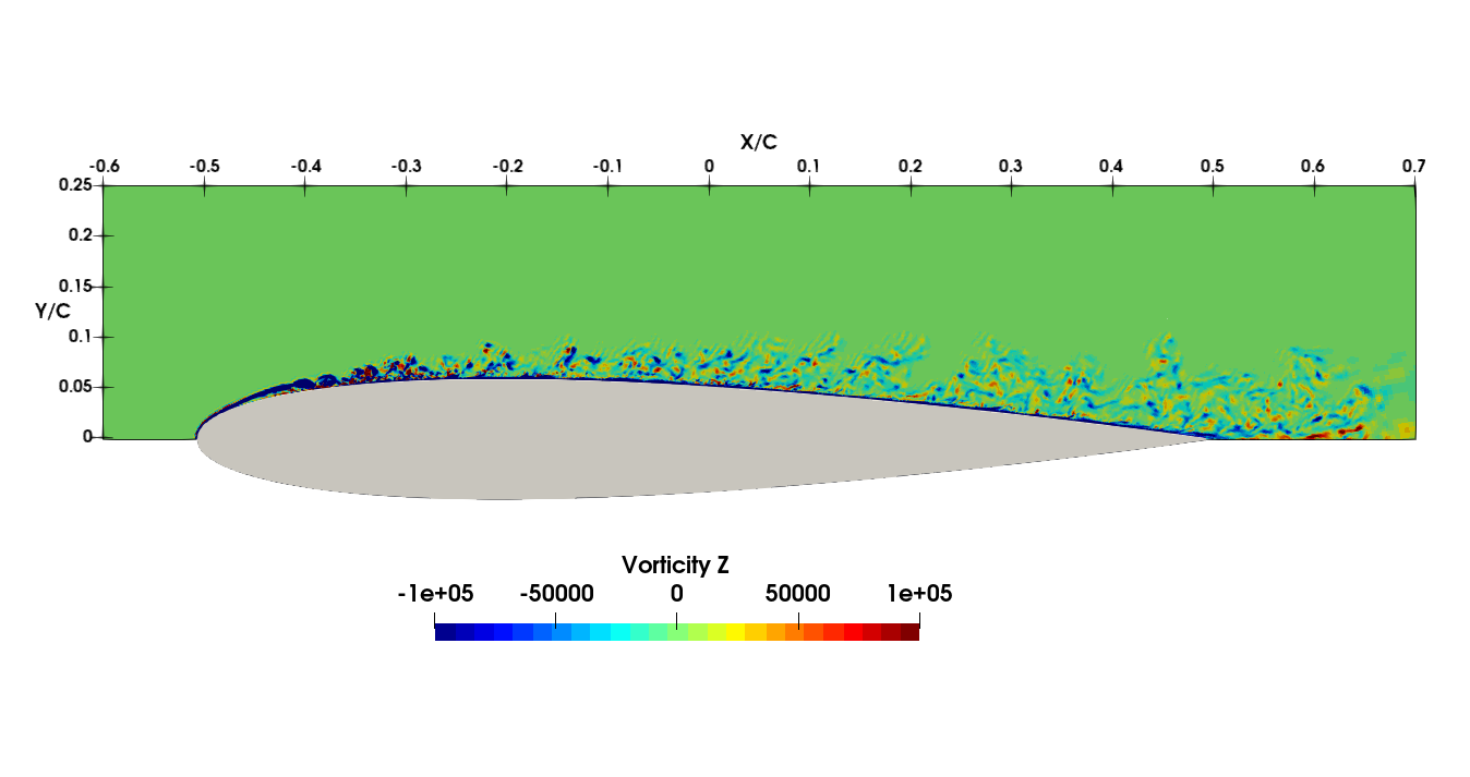
study using AMROC-LBM has also been successfully carried out for a NACA0012
airfoil at Reynolds number 500,000, Mach number 0.22 and angles of attack 0°
and 10°, Fig. 3 and 4. The AMR has been shown to improve mesh resolution
where needed, without interfering with results, Fig. 5.
Simultaneously, within our LBM team, we are developing and improving our in-house
code AMROC for LBM simulations. This includes working on collision operators,
LES models and boundary conditions.
 |
|
Figure 1: LBM-LES simulation of a porous medium made
of spheres. Instantaneous Uz velocity field and iso-contour of the vorticity
norm.
|
 |
|
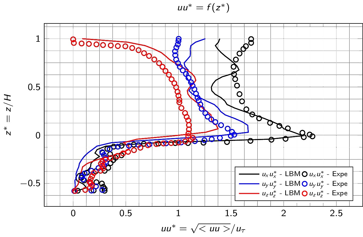
Figure 2: LBM-LES simulation of a porous medium made of spheres. Time-averaged velocity fluctuations in a plane of maximum porosity. |
 |
|
Figure 3: LBM-LES aeroacoustics simulation of a NACA0012
airfoil at Re=500,000, M=0.22 and 10° angle of attack. Instantaneous
z-vorticity field.
|
 |
|
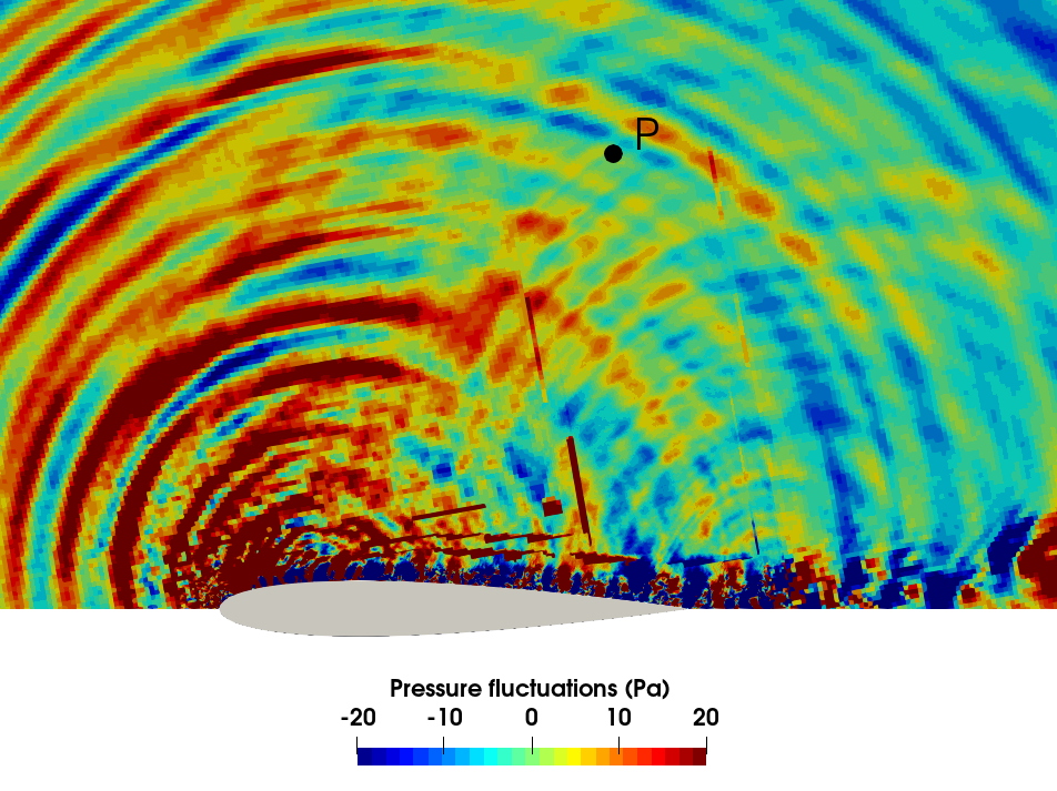
Figure 4: LBM-LES aeroacoustics simulation of a NACA0012
airfoil at Re=500,000, M=0.22 and 10° angle of attack. Instantaneous
pressure fluctuations.
|
|
|
|
Figure 5: LBM-LES aeroacoustics simulation of a NACA0012 airfoil at Re=500,000, M=0.22 and 10° angle of attack. Iso-contour of the vorticity norm and cross-sectional view of mesh levels. |
See Research outputs @Project website oft the University of Southampton
Pure project ID: 519186
Prof. Bharath Ganapathisubramani
![]()
This project is part of the EPSRC program grant Transpiration Cooling Systems for Jet Engine Turbines and Hypersonic Flight (EP/P000878/1).
When hypersonic vehicles are flying through the atmosphere tremendous amount
of heat loads can be experienced. Thermal protection systems (TPS) are designed
to sustain these thermal loads. Traditionally, ablation based TPS have been
used to prevent the heat to get to the internal structures.
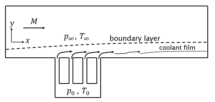
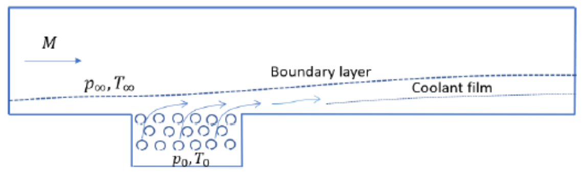
In the alternative strategies, a coolant is directly injected into the Hypersonic
flow, which forms a thin coolant layer on the surface providing cooling. These
strategies are supposed to reduce weight and overall cost of TPS. However, it
is noted that the direct effusion of coolant fluid through the holes (also called
effusion) is not very effective in providing the film cooling as it leads to
separation and enhanced mixing inside the boundary layer. To avoid this, a new
cooling strategy is explored in the present project, where transpiration-based
cooling is envisaged to provide the thermal protection. In this strategy, the
coolant is injected into the flow through a porous layer. This leads to a gradually
and more uniform distribution of the coolant into the boundary layer and hence
higher effectiveness.
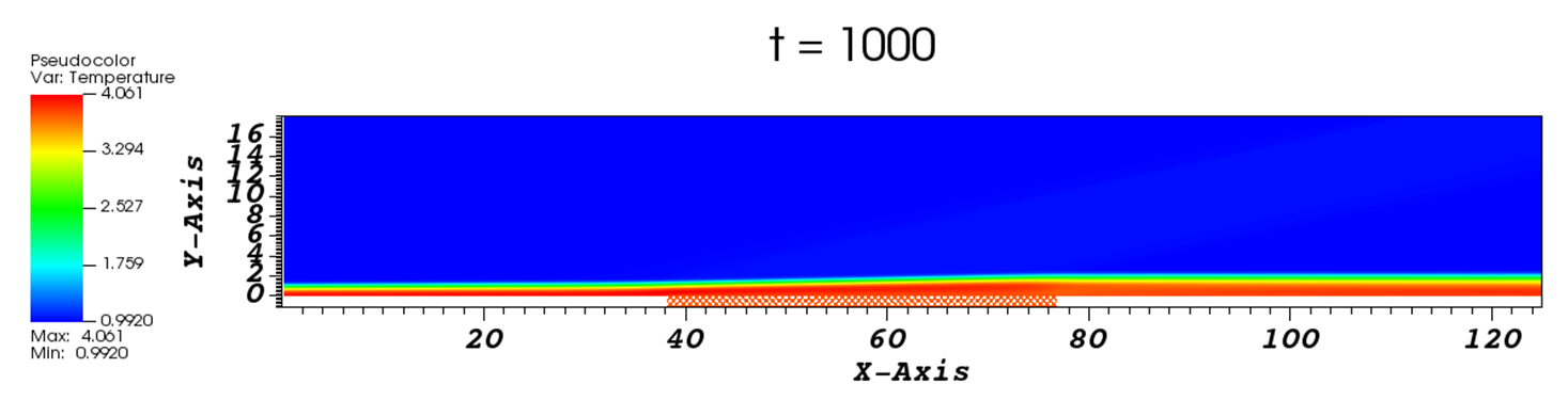
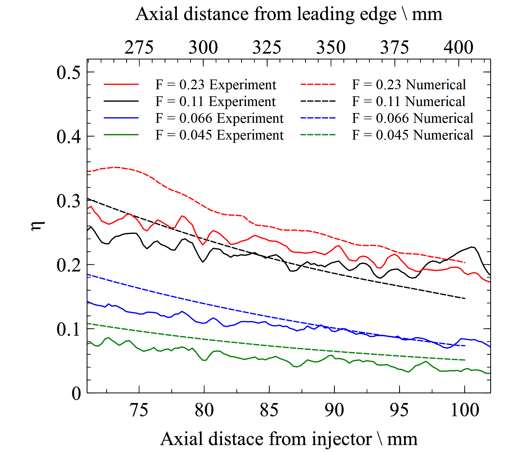
The project aims at providing numerical solution to the challenging problem
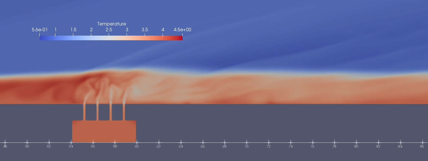
of transpiration cooling in conjunction with the experimental results provided
from the Oxford University's Hypersonic Group. Various injection strategies
of coolant-injection are tested, such as slot injection (Fig. 1) and injection
using a porous-layer (made-up of ultra-high temperature ceramic (UHTC) material,
Fig. 2). The cooling effectiveness of the slot injection is shown in Fig. 3,
showing a good match with the experimental results (with similar set-up) for
different blowing ratios.
|
(a)
Or
(b) |
|
Fig.1: (a) Schematic of a slot injection, (b) Coolant
injection through slots into the hypersonic flow.
|
|
|
|
Fig. 2: (a) Schematic of a porous layer, (b) Coolant
injection through porous layer into the hypersonic flow.
|
 |
|
Fig. 3: Cooling effectiveness of the slot injector with various blowing ratios compared against the experimental results, showing a good match. |
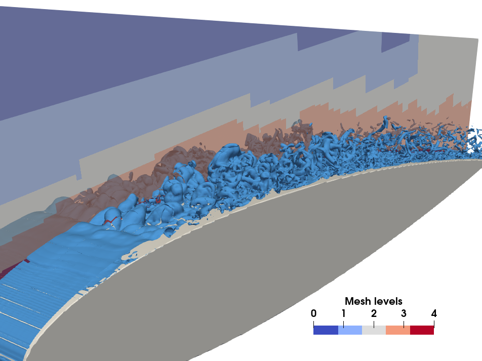
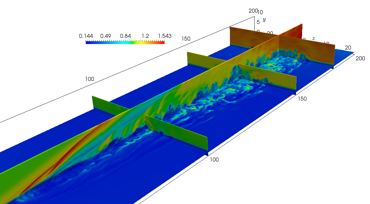
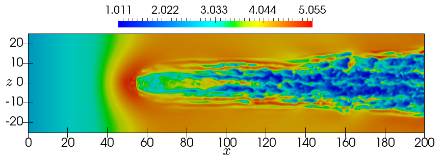
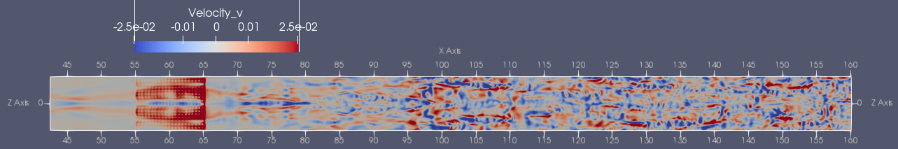
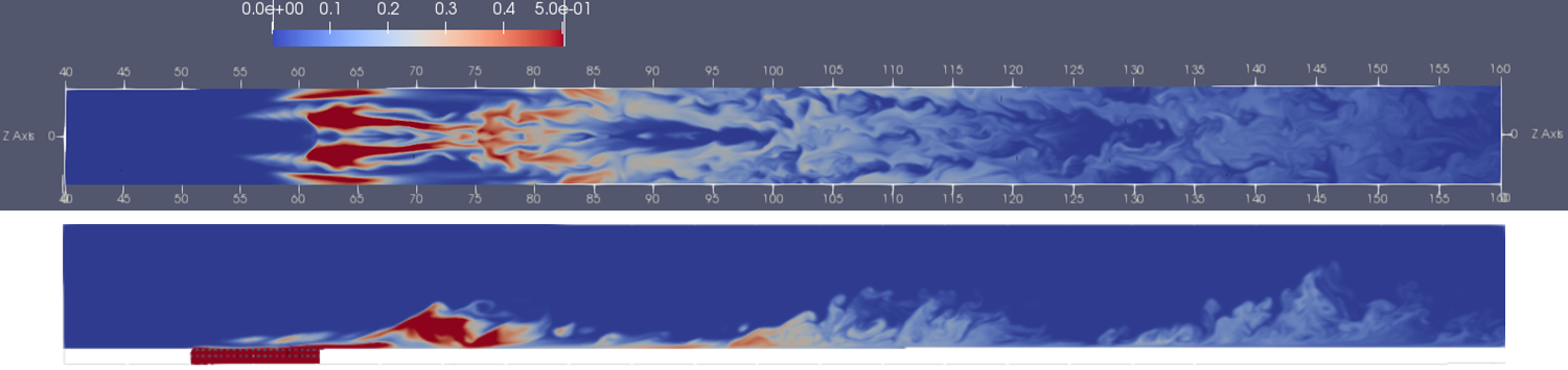
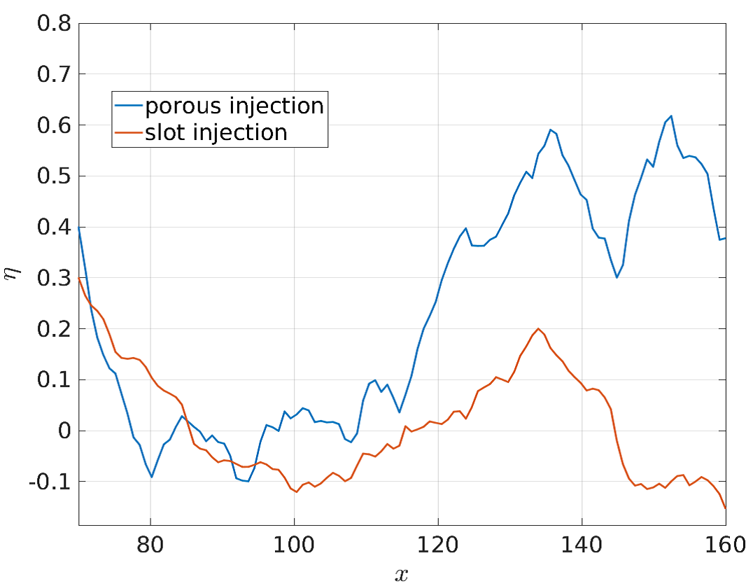
The set-up with porous-layer injection is also studied where the porous layer is modelled as staggered layers of cylinders/spheres in 2D and 3D, respectively. The wall-normal component of velocity is plotted in Fig. 4 (a) for 3D case, which shows the top view of the flow at wall. The fluid close to the porous layer is relatively smooth while it transitions to turbulence farther downstream. A comparison with the slot injection case with similar mass flow rate is shown in Fig. 4 (b) in terms of cooling effectiveness, which shows the greater effectiveness of porous layer in achieving lower wall temperatures specially farther downstream.
|
(b)
(c) |
|
Fig. 4: (a) v-component of velocity at wall, showing
transition to turbulence at downstream locations, (b) coolant concentration
from top and side view, (c) cooling effectiveness comparison with the
slot case showing far better results with porous layer injection.
|
Compressible Navier-Stokes equations in 2D and 3D are solved in the finite volume
framework AMROC in Cartesian reference system, where spatial derivatives are
evaluated using a specially designed hybrid WENO-CD scheme (up to 6th -order
accurate) and 3rd order Runge-Kutta method for time integration. Additionally,
structured-adaptive-mesh-refinement is achieved using AMROC framework, to capture
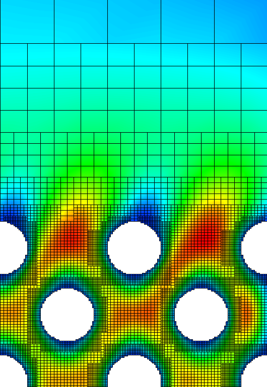
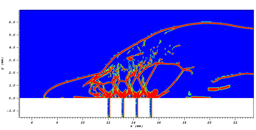
the region of strong gradients dynamically in the flow. Figure 5 (a) shows the
different levels of refinement which can be achieved in the AMROC and (b) shows
the switch function (flag) used to identify the regions of the strong gradients
and according activates the WENO scheme in the regions of gradient while the
central scheme is employed in the smother regions.
|
(a)
(b)
|
|
Fig. 5: (a) Mesh levels in AMROC shown through the
porous layer and (b) WENO-CD switch flagging detecting the shock structures
|
See Research outputs @Project website of the University of Southampton
Pure Project ID: 516448
Pushpender
Sharma
Prof.
Neil Sandham
![]()
The aim of this Dstl-funded project (Dstl - 20200512) is to build a simulation database of compressible channel flow over several irregular rough surfaces for a range of friction Reynolds and Mach number. The goal is to understand how roughness influences the flow topology and key surface parameters such as heat flux and wall shear stress.
Currently, Direct Numerical Simulation (DNS) and experimental studies of rough
wall flows are mostly limited to the incompressible flow regime. The limited
data for high speed flows has resulted in most models being developed for RANS
computation to be based on results from incompressible studies. There is evidence
to suggest that compressibility effects can be important. For example, experimental
investigations have shown that shock and expansion waves, which span the boundary
layer, can be produced by a rough surface in supersonic flow. Furthermore, only
a relatively small number of experimental and DNS studies have investigated
the heat transfer effects due to roughness. Some existing experimental and DNS
studies have suggested that using the Reynold's analogy to calculate heat transfer
may not give accurate results for rough surfaces.
In light of these issues, there is a need to increase the understanding of the
effects of roughness on high speed boundary layers, so that models can be tested
and developed. This research will investigate, through the use of DNS, to assess
the influence of roughness on the skin friction, heat transfer and flow topology
in compressible, non-adiabatic flow.
|
|
|
Caption: Channel Flow Setup
|
|
|
|
Caption: Rough Channel Flow
|
Pure project ID: 520287
Raynold Tan
Ralf Deiterding (PI)
![]()
A modular laboratory rotating detonation engine (RDE) for combined mass flow rates below 10g/s has been designed and tested. To our knowledge, this is the first successful RDE experiment in the UK. Design and experimental setup have been developed over three successive final year group design projects in aerospace engineering.
A rotating detonation engine utilises a detonation wave which travels azimuthally
within an annular chamber to expel propellant and generate thrust. The chamber
is formed by two coaxial cylinders, and the radial gap between them, referred
to here as the chamber width, forms the chamber. The detonation wave is maintained
by constantly feeding fuel and oxidiser into the chamber, thus ensuring that
there is a constant mixture of reactants in front of the detonation.
RDEs are of interest due to their potential efficiency gains in hypersonic propulsive
systems. The efficiency gains of a detonation engine are due to the greater
temperature and pressure increase produced by detonation over deflagration,
allowing more work to be extracted from the same amount of propellant.
Constructed as a small-scale laboratory demonstration project, the objective
was to utilize as small mass flow rates as possible. This naturally lead to
the adoption of a RDE rocket design supplied with pure oxygen. For safety and
ease of handling ethylene was selected as fuel.
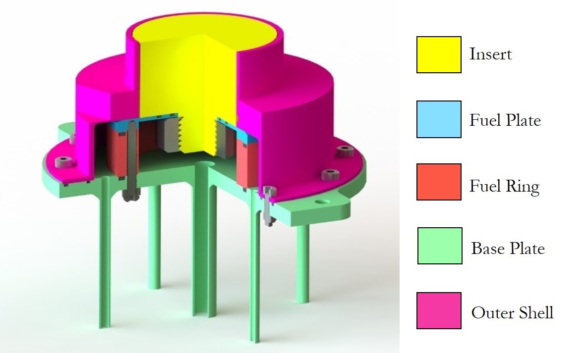
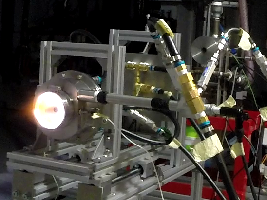
The annular slit size between insert and outer shell (Fig. 1) in successful
tests was 1.2mm. The detonation wave is initiated by pre-detonator tube with
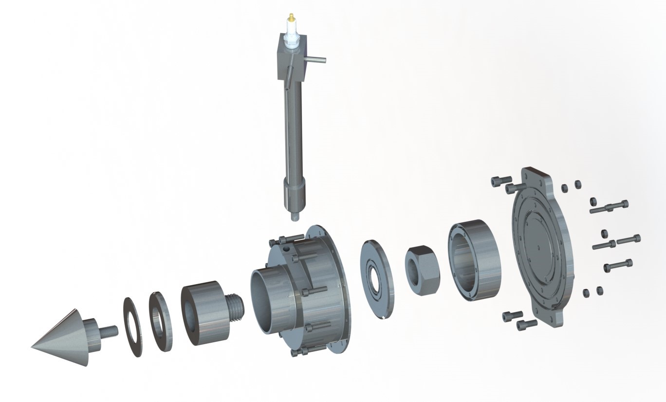
internal Shelkin spiral; several aerospike nozzle attachments (Fig. 2) lead
to considerable thrust increases. During the experiments (Figs. 3 and 4) the
engine was mounted on rails to allow measuring the thrust. Depending mass flow
rates between one and three simultaneously spinning detonation heads have been
observed by high speed photography and confirmed by analysis of the pressure
signals measured with a high-frequency transducer in the chamber.
|
|
|
Fig. 1: Design of the miniature RDE.
|
|
|
|
Fig. 2: Exploded view of parts including pre-detonator
tube and aerospike nozzle with constrictor rings.
|
|
|
 |
|
Fig. 3: Operation with 9.5g/s. Visible flame (left) and high-speed image showing three spinning detonation heads (right). |
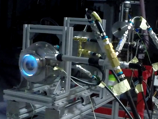
|
|
|
 |
|
Fig. 4: Operation with 3.5g/s. Visible flame (left) and high-speed image showing one spinning detonation head (right). |
|
![]()